 Free Shipping Over$200

- Products
- Marking
- Alternative

Holding Power Integrity on an AI Board with the Right Passives
The cheapest parts on an AI board stand guard over the dearest one. A processor that costs tens of dollars holds its voltage because capacitors that cost cents sit where they belong, and an inference that completes cleanly does so because an inductor was chosen for the current it carries rather than the number on its label. Power integrity is the discipline of making the supply look stiff to silicon that yanks on it, and the parts that do the work are passives: capacitors, inductors, beads, the unglamorous bottom of the bill of materials.
The work has a shape. The converter regulates slowly, the silicon demands quickly, and the gap between those speeds is bridged by stored charge sitting close enough to be useful. Every passive on the rail is a reservoir or a gate somewhere along that path, each effective over its own band of frequencies, and the design question is whether the chain of them hands the load a low impedance from DC up to the fastest edge the silicon produces.
Impedance is the whole game.
A target the rail has to meet
The clean way to think about a power distribution network is as an impedance the load looks into. Divide the allowed voltage ripple by the step current the silicon draws and the result is a target in milliohms; hold the network under that target across frequency and the rail holds its voltage no matter when the load fires. The figure turns a vague wish for a quiet rail into a curve a design can be checked against, and it makes every capacitor's job concrete: each one holds the impedance down over its own slice of the spectrum, and a slice nobody covers shows up later as ripple at exactly that frequency.
The target also says where the effort goes. Meeting milliohms at low frequency is a matter of enough bulk capacitance, which is cheap and roomy; meeting it at hundreds of megahertz is a matter of geometry, which is designed and cannot be bought later. Reading the curve from left to right is reading the board's layout problems in advance, and the designs that pass on the first spin are the ones that treated the right-hand end as a floorplan question rather than a parts question.
Decoupling against the fastest edges
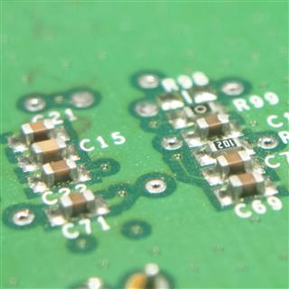
Closest to the silicon sit the smallest capacitors, and their placement is the least forgiving job on the board. When a processor's clock gates open and a few amps appear inside a nanosecond, the only charge that arrives in time is the charge stored within millimetres of the pins. Decoupling around a high current processor is the full treatment of that zone, and its rule of thumb survives every revision of the silicon: the faster the edge, the shorter the loop.
The work divides by frequency band, and the parts divide with it. The familiar ladder of values, hundreds of nanofarads for the fast work, single microfarads behind them, tens of microfarads behind those, exists because each value is effective over its own band and hands off to the next as frequency falls. What the data sheet does not say is that the mounting dominates the part. A ceramic capacitor's own inductance is tiny; the pad, the trace, and the via that connect it add nanohenries that swamp it, and a capacitor mounted a few millimetres further from the pin, or through one thin via instead of a stitched pair, stops working at the frequencies it was placed for. The honest placements put the smallest values on the underside of the board directly opposite the power pins, with via pairs that are short and fat, and accept whatever the assembly cost says about that choice. Ceramics carry their own fine print as well: a part marked ten microfarads delivers a fraction of it with the rail's DC bias across it, the loss depends on the dielectric class, and a derating the designer never checked is a target the network silently misses. Class 2 dielectrics trade capacitance for temperature and bias stability, so the value in the simulation has to be the value at the operating point, not the value on the label. Temperature and ageing stack on top of bias: the same class 2 part loses more of its value hot, and a network sized at the bench in spring can sit closer to its target than anyone planned in an enclosure at full load in summer. The count of capacitors is the last lever, since paralleling parts divides their mounted inductance as well as adding charge, and four small ceramics through good vias outperform one large one through a lazy route at every frequency that matters. None of these effects appears on a schematic, all of them appear in an impedance sweep, and the gap between the two is where first-spin boards fail their ripple measurement.
The planes are the last capacitor. A power plane and a ground plane stacked closely make a distributed capacitance with almost no inductance, and at the frequencies where even the best-mounted ceramic has given up, that plane pair is the only thing still holding the impedance down. Under a large package, the via field that drops the pins onto those planes is part of the decoupling network whether anyone designed it or not.
The common failure is ritual. A capacitor per pin, copied from a reference design with a different stackup and a different load, satisfies a checklist and misses the target; the network that works is derived from the impedance curve of this board, with this layer stack, against this silicon's edges.
Decoupling is geometry first and parts second, and it is the geometry that cannot be patched after the boards arrive.
The inductor the converter leans on
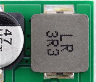
Every point-of-load converter on the board leans on one magnetic part, and the rail inherits its honesty. Choosing the inductor for a point of load converter starts from the ripple current the switching frequency and voltage step impose, which sets the inductance, and then runs straight into the two current ratings that decide whether the part survives the application.
The ratings answer different questions. The thermal rating says what continuous current warms the part to its limit; the saturation rating says where the core stops being an inductor. A load transient rides the inductor above its average current, and a hard-saturating ferrite that crosses its limit during that excursion loses its inductance exactly when the rail needs it, letting the ripple spike and the converter stumble. Soft-saturating composite cores fade gradually instead, which is why they forgive a transient-heavy load even when their headline numbers read worse on paper.
Resistance does quiet damage. The winding's DCR burns conduction loss and contributes to droop under load, and the difference between two otherwise similar parts is often the difference between a converter that meets its efficiency curve and one that runs warm for no visible reason. Shielding decides how much of the switching field leaks into neighbours, height decides whether the part fits under the heatsink, and an unshielded inductor saved for cents beside a sensitive trace is a noise problem bought deliberately.
The selection that holds up is sized for the transient peak against saturation and for the continuous load against temperature, with the DCR counted in the loss budget rather than discovered in the thermal camera.
Bulk that buys the ride-through
At the slow end of the network sits the bulk capacitance, the reservoir that carries the rail between the moment a load step lands and the moment the converter's loop catches up. Where bulk capacitance buys ride through on a load step is the sizing story: the charge the load pulls during the loop's response time, divided by the droop the rail can afford, is the floor for how much capacitance has to stand behind the rail, and it is a number a designer can calculate before the first prototype rather than tune after it.
The technologies split the job. Polymer parts hold low ESR in small volume and shrug off ripple current; tantalums pack capacitance densely and ask in return for respect of their voltage derating; aluminium electrolytics are the cheap deep store that ages with temperature and time. ESR itself is not purely an enemy, since a little resistance damps the network and a bank of perfectly clean capacitors can ring against the planes; the bank that behaves is the one designed with its losses counted rather than minimised blindly.
Placement closes the loop. Bulk at the converter output stabilises the loop that regulates; bulk at the load side feeds the step before the trace inductance lets the converter help. A long, thin path between the two turns good capacitance into a reservoir behind a narrow door, and the milliohms of that path belong in the same budget as the parts.
The bead that quiets a sensitive rail
One passive on the rail is there to block rather than store. A ferrite bead is a resistance that rises with frequency, and placed between a noisy switching rail and an analog island it burns the ripple as heat instead of passing it along, which is why it guards the supply pin of an ADC, a PLL, or an image sensor's analog side. How a ferrite bead tames supply noise carries the details and the trap: a bead's impedance against the capacitors behind it forms a resonant circuit, and an undamped choice can amplify noise at one frequency while killing it everywhere else, turning the filter into the problem it was meant to solve. The bead that earns its place is selected against the actual noise spectrum, checked for resonance with the island's capacitance, derated for the DC it carries, and given a voltage drop budget, since its resistance at DC sits in series with a rail that may already be counted in millivolts. Used with that care it is the cheapest quiet a mixed-signal board can buy; used by ritual it is a coin-sized oscillation waiting for the right load current to find it.
What decides it
The impedance curve decides the network, and it is read from the silicon outward. The fastest edges are served by geometry at the pins, the middle by the ceramic ladder, the slow end by bulk, and a network designed in that order meets its target once instead of being patched toward it.
Mounting carries the same weight as the part. The capacitor value, the inductor rating, and the bead's curve all assume the layout lets them act, and the nanohenries of a careless via are a tax every part on the rail pays.
Supply finishes it, in a corner of the catalogue with its own habits. Ceramic capacitors move through shortages by case size and dielectric, inductors by core material, and the design that names a second source in the same footprint and the same class, before the first build, is the one that rides through the next allocation season still shipping.






