 Free Shipping Over$200

- Products
- Marking
- Alternative

Stretching a Battery Device Runtime With Power Management
On a battery device that spends its life asleep, the power management decides how long the cell lasts, and the figure that matters is not efficiency at full load but the current the regulator draws while the device sits doing nothing. A part that is ninety percent efficient at a hundred milliamps yet burns twenty microamps at idle can flatten a coin cell faster than the application ever does, which is the reversal that catches a team used to designing boards that stay plugged in.
That turns the power management parts into a real set of choices rather than a line copied off the last design. The regulators, the load switches, a fuel gauge, and a harvester where the device has one each pull on the energy budget, and picking them for a sleepy node follows rules that do not match the ones for a mains powered board, where idle current never counted and efficiency at full load was the whole of the story. A part that looks identical on a parametric search can differ by an order of magnitude in the one figure that sets the battery life, and reading the wrong column is how a design quietly misses the runtime its datasheet seemed to promise.
Quiescent current is the number
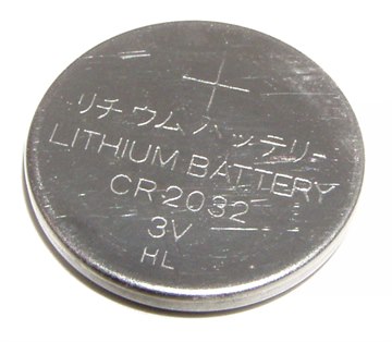
Quiescent current, the current a regulator consumes to keep itself running with little or no load on it, sounds like a footnote and is the headline for a device that sleeps. A node that wakes for a few milliseconds a minute spends almost all of its time drawing only its sleep current, and the regulator's own quiescent draw is a fixed part of that floor, flowing every second whether the device has anything to do or not. A regulator with a quiescent current of ten microamps, sat under a load that averages a few microamps, dominates the budget by itself, so the part has to be chosen for what it costs at no load long before what it costs at full load enters the conversation. The bold efficiency figure on the datasheet, by contrast, is taken at a load the sleepy device almost never reaches.
The way to see it is to weigh the two states the device lives in. Active current multiplied by the slice of time spent awake, added to sleep current multiplied by the far longer slice spent asleep, gives the average the battery feels, and on a node that wakes once a minute the sleep term wins by a wide margin. Shaving milliamps off the active draw buys little when the device is awake for a thousandth of its life, while shaving microamps off the floor buys years.
The trap is that the efficiency number printed large on a datasheet is measured at a load the sleepy device sees for a few milliseconds an hour. A switching regulator rated at ninety five percent at half an amp can fall to a fraction of that at a hundred microamps, where the energy it spends switching swamps the energy it delivers, so a part that looks excellent on the front page becomes the wrong choice for a node whose average load sits a thousand times below the test point. This is the heart of stretching the battery life out of the right power management chip: read the quiescent current and the efficiency at the load the device runs at, which for a sleepy node means the light load and no load columns buried in the table, not the bold figure at the top. The newer generation of parts is built around exactly this, with quiescent currents down in the hundreds of nanoamps and switching schemes that pulse only as often as a small load demands, so a buck can finally compete with an LDO on idle draw while keeping a switcher's efficiency when the radio wakes and pulls real current. The architecture that falls out of this reading is usually a split one: a small, frugal rail kept alive at all times to hold up the parts that must never lose power, and larger rails switched off between bursts of work, so the always on path is sized for nanoamps and the heavy path exists only when something needs it. Getting the always on rail wrong is the quiet way a design misses its battery target by a factor nobody can explain from the schematic, since every part looks right and only a current measurement at true idle shows where the charge is leaking away. That measurement is its own small challenge, because an idle draw of a few microamps sits down near the noise of an ordinary bench meter and often needs a dedicated low current range, or a sense resistor sized for the sleep state, before it reads at all. The discipline that prevents it is to budget the sleep state first, name the few things that have to stay powered, and choose the part that holds them up for the lowest standing draw, then treat everything else as a load to be switched off rather than a load to be turned down a little.
The always-on rail
The rail that never turns off sets the floor for the whole device, so it earns the closest look. The current it carries is small, a microcontroller in deep sleep and perhaps a real time clock, yet it flows without pause, and the regulator holding it up is chosen on quiescent draw and on noise ahead of anything else.
When that rail also has to be clean, a low noise LDO earns its place on its own terms. The LP5907SNX-3.0/NOPB holds up a quiet always on rail, a low noise regulator with high power supply rejection that suits a sensitive analog or radio supply where the ripple of a switcher would fold straight into the signal, drawing little enough at idle to sit on an always on path without spoiling the budget. It trades the efficiency of a switcher for quiet and for a low parts count, which is the right trade on a light rail where the dropout loss is small and a clean supply matters more than the last point of efficiency.
Where the job is a small, frugal rail with no noise concern, the part gets plainer still. The MCP1700 covers a low quiescent small current LDO, a low cost regulator that delivers a modest current at a low quiescent draw, which suits powering a microcontroller and a sensor on a node where the input sits close enough to the output that the dropout loss of an LDO stays small. It is the default when the rail is light and the input headroom is tight, the part picked when simplicity and price outweigh the efficiency a switcher would add.
When the drop from input to output grows large, an LDO burns that difference as heat and a buck becomes the efficient answer, on the condition that it idles cheaply. The TPS62840 gives a buck with ultra low quiescent current, a step down regulator whose quiescent draw sits in the low hundreds of nanoamps, which lets a design take the efficiency of a switcher across a wide input range without paying the idle penalty older bucks carried. It is the part that makes a switched always on rail practical on a battery, where a few years ago the choice would have defaulted to an LDO purely to hold the idle current down, and it changes the split architecture by letting the frugal rail run as a switcher when the input demands one. A wide input that falls as the battery drains is exactly where it pays.
Cut what sleeps
Anything that draws nothing between bursts of work should have its power removed, not lowered. A load switch does it.
Boost, harvest, gauge, and switching off the rest
A battery's voltage falls as it discharges, and a device that needs a steady rail above or across that falling voltage needs a regulator that can both step down and step up. The TPS63070 gives a node a buck boost, holding its output steady whether the cell sits above or below the target, which suits a single cell device that has to keep working from a fresh cell down to a nearly flat one rather than dropping out when the voltage crosses the rail. It earns its added complexity on any output that has to outlast the battery's full discharge curve, and it removes the temptation to oversize the cell just to stay above a fixed regulator's input window.
Where the device gathers its own energy, the front end has to make use of a tiny, irregular input. The BQ25570 harvests tiny energy into a usable rail, starting from input levels low enough that a small solar cell under cloud or a modest thermal gradient still yields something, with maximum power point tracking to draw as much as the source can give and a charger to bank it into a cell or a capacitor the device runs from. It turns a source too weak to use directly into a rail a node can live on.
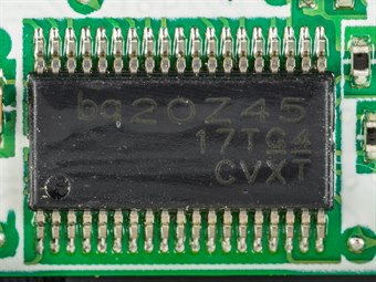
Knowing how much charge is left is its own job, and on a battery device guessing from terminal voltage alone is unreliable. The MAX17048 serves as a fuel gauge for a battery device, tracking the state of charge with a model that corrects for load and temperature so the device can report a real battery percentage and warn before it dies, rather than reading a sagging voltage that lies under load and recovers at rest. It draws little enough to stay powered on the always on rail, and it earns its place wherever a wrong low battery estimate costs more than the part, on a device that has to manage a clean shutdown or a last message before the cell gives out.
Back to the load switch, the part that removes power rather than lowering it. The TPS22918 cuts idle sections as a load switch, a controlled switch that disconnects a sensor, a peripheral, or a whole subsection of the board when it goes idle, taking its leakage out of the sleep budget instead of trusting it to a low power mode that still draws something. A section fully switched off beats the same section idling every time the device is counting microamps.
Across the whole set the discipline holds: size the always on path for the idle current, switch off everything that can be switched off, and read every part at the load the device runs at rather than the one a datasheet leads with. The boost holds the rail up as the cell sags, the harvester refills it where there is energy to gather, the gauge says how much is left, and the load switches take the idle sections out of the budget altogether. Get those four right around a frugal always on rail and the battery is spent on the work, not in the gaps between it, which on a sleepy device is where the charge would otherwise quietly go.






