Free Shipping Over$200

- Products
- Marking
- Alternative

Planning Long Term Supply for a Power Module Part
Planning Long Term Supply for a Power Module Part
A long-life device can fail its supply plan long before the circuit stops working. The board may pass validation with one power module, a fixed footprint, a known capacitor bank and a known thermal path. Years later, the same module may sit behind allocation, lifecycle pressure, packaging change, plating change, manufacturing-site change or a substitute request that arrives after the enclosure, qualification file and safety report are already frozen. That is why a power module should be planned as a controlled board-level system rather than as one line in a bill of materials.
The phrase power module can cover many forms. It may be a compact DC-DC module with an inductor inside, a high-current point-of-load stage, an isolated converter, a brick-style supply, or a regulator module tied to a carrier board. In each case, the part carries electrical function, mechanical volume, heat flow, pin assignment, assembly constraints and sourcing risk in one package. A last-minute replacement can disturb all of those layers at once.
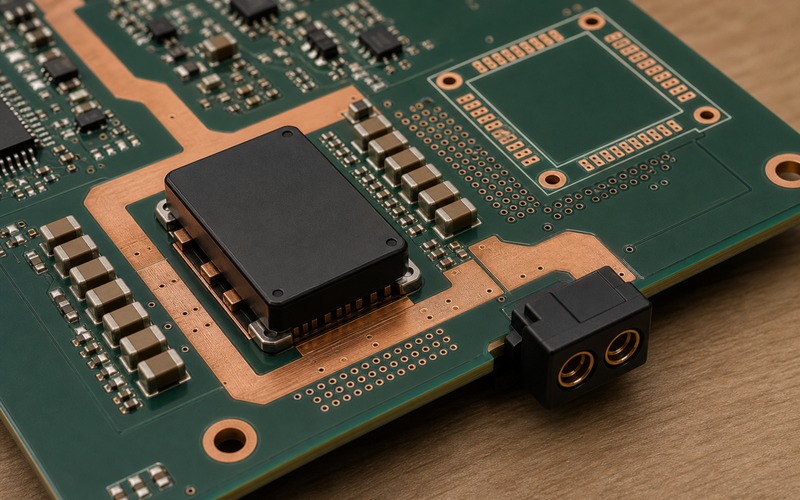
Start With the Released Power Architecture
The first record should define the power architecture that the module belongs to. Write the upstream source, input range, output rail, maximum operating current, peak current, load step, start-up sequence, enable logic, protection expectation and the load that depends on the rail. A module feeding a processor core has different risk from a module feeding a sensor heater, motor-control rail, isolated interface, communication card or distributed auxiliary bus.
Do not let the module approval stand alone. The released file should name the input capacitors, output capacitors, bulk storage, sense routing, fuse or protection device, connector direction, board copper, airflow assumption and measurement points. These surrounding parts often decide whether a replacement can be accepted without a new board spin. A module with the same voltage and current rating may need a different minimum capacitance, a different soft-start condition or a different thermal area.
The system boundary should also include firmware behavior. Some products wait for a power-good signal. Some enable loads in steps. Some read current or temperature before allowing the full load profile. If a future module changes power-good threshold, start delay, fault latch or hiccup behavior, the host can misread the rail. Record the timing and fault behavior while the original module is still easy to test.
Freeze the Mechanical and Electrical Boundary
The mechanical boundary is as important as the schematic. Module height, body outline, pin row, keepout, screw boss, shield clearance, airflow path and connector access should be documented with the same care as voltage rating. Many supply problems are discovered after a purchase team finds a substitute that fits the electrical headline but collides with the enclosure, heat sink, cable bend or automated assembly fixture.
For electrical fit, capture more than input and output voltage. Note UVLO range, enable threshold, output trim range, current limit style, remote-sense option, isolation rating if present, switching frequency range, synchronization option, output ripple, transient response and load-capacitance limits. A substitute that changes any of these values may still run on a bench while failing in the product's cold start, surge test, EMC test or thermal chamber.
Pin compatibility needs a written definition. Same footprint can mean same pad positions, same pin functions, same pin sequence, same land pattern, same height class and same stencil requirement. It can also mean only that the body fits the area. Each candidate part should be checked against the real electrical, thermal, mechanical and sourcing conditions it will face before the board moves into production.
Separate Same Footprint From Same Behavior
Power modules invite dangerous shorthand. A buyer may ask for an equivalent because two parts share an output voltage and a current rating. An engineer may approve a second source because the package drawing looks close. A supplier may quote a replacement because the market name is similar. None of those checks proves behavior on the board.
Same footprint does not prove the same loop dynamics. Output capacitance limits, ESR range, sense routing, compensation method and transient response can change. A processor rail that looks stable at static load may overshoot during enable or droop during an accelerator load step. A communication module may reset if a support rail has a longer soft-start ramp. An isolated converter may pass DC testing while failing insulation spacing or common-mode noise limits.
Same rating does not prove the same heat result. Module loss changes with input voltage, output voltage, load profile, switching method, magnetics and package construction. The released board copper may be enough for one module and marginal for another. If the enclosure uses a thermal pad or airflow guide, the contact point and surface flatness become part of the component approval.
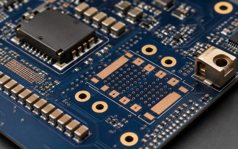
Build the Approved Alternate Before It Is Needed
A long-term supply plan should name at least one approved alternate path while the engineering team can still test it calmly. The alternate may be a pin-compatible module, a small layout variant, a daughterboard, a different manufacturer family, or a controlled redesign already held in reserve. The path depends on product volume, certification burden, service life and the cost of requalification.
The approved alternate should include the exact orderable part, required surrounding components, derating limits, layout notes, assembly notes, firmware notes and test evidence. If a substitute needs a changed output capacitor set, changed trim resistor, changed enable pull-up, changed heat spreader or changed connector height, record that requirement in the alternate file. This prevents a future purchase from treating the module alone as the full answer.
Testing should copy the hard operating corners of the product. Check low input, high input, cold start, hot soak, fast load step, slow load increase, sleep-to-active transition, fault recovery, short-circuit response, EMC-sensitive mode and any safety-related condition. Record the waveforms, current limit behavior and temperature measurement points. A passing note without test context does not help a later engineer approve a sourcing change.
Watch Lifecycle, Qualification and Process Change Notices
Power modules often sit in products that sell for many years. The file should include a lifecycle owner and a review interval. The review is not a promise of future availability. It is a discipline: check manufacturer status, package notes, quality notices, assembly-site changes, material changes, data sheet revisions, safety-file status and the supplier route used by the business.
Process changes can matter even when the part number remains the same. A changed magnetic material, molding compound, plating stack, test limit or production site can shift thermal behavior, soldering behavior, EMI margin or reliability evidence. Keep the manufacturer's notices with the internal qualification file, and decide which changes require engineering review before the next build.
For regulated or safety-sensitive products, the module may also be tied to certification evidence. Isolation spacing, insulation system, flammability rating, leakage current, creepage, clearance, surge test and EMC reports may depend on the original part construction. A substitute can force a documentation update even when the schematic pin names stay unchanged.
Keep Thermal and Safety Evidence With the Part
Thermal evidence should travel with the module approval. Record ambient condition, enclosure state, airflow, load profile, input voltage, output current, board orientation, copper layer assumption, measurement tool and measurement location. A temperature number without those conditions is hard to use during a sourcing event.
Safety margin should also be visible. If the module handles external power, high voltage, isolation, field wiring or a rail that leaves the board, document protection devices, spacing, fuse coordination, connector rating and fault energy. A new module can change the way faults clear, the way the rail restarts or the way heat concentrates near plastic parts. Those changes need review before release.
Derating rules should be plain. State the allowed input range, sustained load, peak duration, ambient ceiling, required copper, required airflow and required capacitor set. If the module is accepted only in a product with a heat spreader or forced airflow, say that directly. A future use in a sealed product should then trigger a fresh review instead of borrowing an unrelated approval.
Purchasing Needs Boundaries, Not Guesswork
Purchasing support works better when the engineering boundary is clear. The sourcing note should list the approved part, acceptable suffixes, approved alternate, disallowed substitutions, drawings that must match, and tests that must be repeated after any change. It should also state which questions require engineering review before a purchase decision.
Do not use vague replacement language for a power module. If a candidate is approved for service builds only, say so. If it is approved only after a capacitor change, say so. If it fits the voltage but not the footprint, say so. If it is an electrical redesign path rather than a purchase substitute, say so. Clear words prevent a schedule issue from becoming an uncontrolled board change.
A useful sourcing request includes the exact released part number, output rail, estimated use case, required qualification level and any known alternate list. The response can then focus on package, suffix, lifecycle status, manufacturer route, documentation and engineering review needs. That is different from asking for a generic equivalent, which tends to hide the board conditions that make the part risky.
The same boundary should be visible to quality and production teams. Incoming inspection can check body size, terminal finish, labeling format, packaging condition and certificate trail, while production can watch solder wetting, coplanarity, screw torque, thermal pad contact and reflow exposure. When those checks are written beside the approved module, a sourcing change is less likely to enter the line as a silent experiment.
For service and repair programs, keep the module decision tied to the product revision. A replacement accepted for one hardware revision may depend on a different capacitor bank, a changed screw boss, a new thermal pad or a firmware setting that does not exist on an older unit. Revision control protects field repairs from mixing electrical decisions across board versions.
Final Long Term Supply Checklist
Before a power module is released for a long-life device, confirm the exact part number, suffix, package, height, footprint, pin functions, input range, output setting, load profile, start-up sequence, protection behavior, required capacitors, trim network, enable logic, power-good behavior, thermal path, copper area, airflow condition, connector orientation, fault energy, safety evidence, lifecycle owner and approved alternate path.
Keep the evidence in one place: board drawing, schematic, layout note, test waveforms, thermal images, measurement points, sourcing boundary and approved substitute path. That record gives engineers and buyers the same map when the original module faces lifecycle pressure, supplier change or a controlled redesign request. The goal is not to freeze a single part forever. The goal is to keep the product buildable without losing the electrical, thermal and safety assumptions that made the original design pass.