 Free Shipping Over$200

- Products
- Marking
- Alternative

The Sensing Approaches for Flow and Liquid Level
No flow meter measures flow. Each one measures something the moving fluid does to a physical quantity it can reach: spins a rotor, carries heat downstream, delays a sound pulse, induces a voltage. The flow rate is computed from that footprint, and the computation leans on assumptions about the fluid itself.
That is the sentence to keep while reading any flow datasheet, because the assumptions are where projects go wrong. A meter that was honest on clean water turns evasive on glycol mix, not because the meter changed but because the viscosity did, and the footprint it reads no longer maps to flow the way the calibration assumed. Liquid level plays the same game one floor up: the sensor measures a distance, a capacitance or a pressure, and the litres the application wants are inferred through the tank geometry and the liquid's behaviour. Pick the principle whose assumptions your fluid can keep, and the rest of the design is arithmetic.
The footprints a liquid leaves
The methods behind liquid flow sensing divide by which footprint they read. A turbine meter puts a rotor in the stream and counts revolutions, each pulse a fixed volume, which is cheap and direct and puts a bearing in the liquid where particles grind it and viscosity bends the pulse-per-litre factor at the low end. An electromagnetic meter drives a magnetic field across the pipe and reads the voltage the moving liquid induces, Faraday's law with the fluid as the conductor: no moving parts, no pressure drop, no obstruction, and a hard requirement that the liquid conduct at all, which water, milk and wastewater do and oils and solvents do not. An ultrasonic transit-time meter fires sound pulses diagonally upstream and downstream and reads the difference in arrival times, a difference the flow itself creates, and the clamp-on versions strap to the outside of an existing pipe without cutting it, which makes them the retrofit favourite; the price is a need for clean, single-phase liquid, since bubbles and solids scatter the beam. A thermal meter heats a point and watches how fast the stream carries the heat away, which resolves trickles the others cannot feel. The old guard, the differential-pressure orifice, squeezes the stream through a known restriction and reads the pressure drop, rugged and standardised and paid for in permanent pumping loss. Five footprints, five contracts with the fluid, and the selection is the act of reading those contracts against the liquid present in the pipe.
Every one of them also assumes a flow profile it rarely sees on a careless install. The textbook parabola of fully developed flow takes a straight run of pipe to form, ten or twenty diameters of it, and an elbow or a half-open valve just upstream leaves the stream swirling and lopsided, which a turbine reads as a few percent of phantom flow and an ultrasonic path reads as a skewed transit time. The fix is plumbing, not electronics: straight run ahead of the meter, or a flow conditioner that combs the swirl out, and the accuracy figure on the datasheet quietly assumes one or the other is there.
Volume is the other trap built into the question. A turbine and an ultrasonic meter report volume per second, and volume is a function of temperature: the same kilograms of fluid swell and shrink as the day warms and cools, so a volumetric reading drifts against what the process chemistry cares about, which is molecules, mass. For liquids the error is small and often ignored. For gases it is enormous, since a gas's density moves with pressure and temperature in the same breath, and a litre of air at the compressor outlet is not a litre at the nozzle. Standard volume, referred to a fixed temperature and pressure, is the usual dodge, and it is only mass flow wearing a volume costume, the density folded into the reference instead of measured live.
Mass flow, where the gas is the point
The SFM3019 measures gas mass flow at low pressure drop, and it is the part to study because both halves of its name are the specification. It is a thermal MEMS sensor: a heater on a membrane, temperature sensors either side, and the mass of gas streaming past skews the heat distribution, so the reading is mass flow directly, no density correction, no pressure and temperature companions doing arithmetic. And it presents almost no resistance to the gas, a pressure drop so small that a patient breathing through it does not feel the instrument, which is the design requirement that built it: it is a ventilator and respiratory part, sized for the flows a lung produces, bidirectional so inhale and exhale read with their signs, fast enough to trace the shape of a single breath, and factory calibrated for air and oxygen with the curves stored on chip. It reports over I²C with the conversion done, the flow already in standard litres per minute and a status word flagging any reading that strays off the calibrated curve. Variants cover different full-scale ranges, so one body suits an adult ventilator or a neonatal circuit, where the flows differ by more than a decade. The same properties that suit a ventilator suit any low-pressure pneumatic measurement that cannot afford to obstruct the line, gas analysis, fuel cells, leak checking, and the part is the cleanest demonstration that for gases, measuring mass beats measuring volume everywhere the molecules are what count.
Thermal mass flow has a rival in the Coriolis meter, which twists a vibrating tube as mass moves through it and reads true mass flow, density and even a hint of the fluid's identity, the reference instrument the cheaper meters are checked against. It is also heavy, costly and a real obstruction in the line, the opposite of what a breathing circuit can carry, which is why the thermal MEMS part owns the low-pressure gas corner a Coriolis tube cannot reach. Both measure mass; they sit at opposite ends of what that measurement is allowed to cost the flow.
The gas does not have to push; the sensor only has to listen.
Level: measuring where the surface is
The non-contact approaches to liquid level sensing exist because touching the liquid is so often the thing the design must avoid: acid that eats probes, food lines that must clean in place, sealed tanks nobody may drill. Capacitive sensing reads level through the plastic wall, electrodes outside, the liquid's dielectric constant signalling from inside, no penetration at all. Ultrasonic time-of-flight fires from the top of the tank and times the echo off the surface, the air-side mirror of the rangefinders used for distance. Radar does the same with microwaves and buys immunity to the vapour, foam and temperature gradients that bend sound, at radar prices. Optical reflection serves the small end, a diode and a detector watching for the surface, blind to dielectric and conductivity yet fooled by a clinging droplet on the window. And weighing the whole tank sidesteps geometry entirely, three load cells reporting mass while the liquid sloshes as it likes, the honest answer for a powder or a slurry no surface method can read, paid for in mounts that must not bridge load away from the cells. Each one measures the surface position or the mass; none measures litres, and the conversion through tank shape is the application's own homework.
The split between ultrasonic and radar over a tank is a budget decision dressed as a physics one. Sound needs the air column to behave, and a tank that runs hot near the roof, or fills with solvent vapour, or grows a blanket of foam, bends or swallows the pulse. Microwaves ignore all three, reflecting off the dielectric step at the surface no matter what floats in the space above it, which is why radar took the refinery and the silo while ultrasonic kept the water tank and the cheaper machine. The number that comes back is the same, a distance to the surface; what differs is how many ways the space above the liquid can lie about it.
Floats and submerged pressure sensors still earn their keep where contact is allowed, a float is unkillable in a sump, and a pressure transmitter at the tank bottom reads the liquid column directly, head pressure proportional to height times density, with the density dependence as the fine print: a hot tank reads lower than a cold one holding the same height. The submersible kind drops a sealed transducer to the bottom on its own cable, a vent tube up the middle cancelling the barometric pressure, and the reading is liquid height once density is known, which keeps it the workhorse of well and reservoir level where a few percent is fine and nothing above the water can be trusted. The non-contact methods dodge that, and trade it for their own sensitivities above the surface. There is no neutral choice, only the set of errors the process finds easiest to live with.
Mounting an ultrasonic level sensor is its own discipline, and the mounting decides more of the accuracy than the sensor does. The transducer rings after each pulse and is deaf until the ringing dies, which creates a blind zone below the face: a surface closer than that distance reads as garbage, so the sensor needs headroom above the maximum level, the one dimension datasheets print and installers ignore. The beam spreads as a cone, and everything inside the cone answers: a ladder rung, an agitator blade, the tank wall on an off-vertical mount, each one a phantom surface for the firmware to reject. The face must aim square at the liquid, since a tilted beam bounces its energy away and the echo comes home weak. Foam is the heartbreaker, a soft absorbent blanket that swallows the pulse and returns either nothing or the foam top instead of the liquid; heavy foam is the cue to switch to radar or capacitive. And the speed of sound itself drifts with air temperature, roughly a sixth of a percent per degree, so a sensor without temperature compensation converts a warm afternoon into a level shift the tank never had.
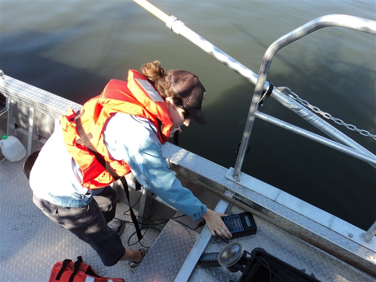
The medium writes the spec sheet
Run the assumptions the other way and the fluid itself picks the technology. Conductive and dirty, the electromagnetic meter is close to unbeatable, which is why it owns water treatment. Clean, non-conductive hydrocarbons sit in turbine and ultrasonic territory. A retrofit on a pipe that cannot be cut argues clamp-on ultrasonic. Trickle-scale dosing argues thermal. Gas argues mass flow on principle, and a breathing circuit argues the low-pressure-drop kind specifically. Bubbles are the universal saboteur: they scatter ultrasound, they perforate the conductive path an electromagnetic meter drives its current through, they let a turbine spin on air it counts as liquid. A fluid that arrives as a two-phase froth defeats the catalogue, and the honest fix is upstream, a degassing pot or a straight calming run, not a cleverer meter. Air entrained at even a few percent by volume reads as flow that is not there on a thermal or turbine meter and as signal dropout on an ultrasonic one, which is why a custody-transfer skid puts an air eliminator ahead of the meter as a matter of course.
Calibration is the quieter half of accuracy. A turbine's K-factor is stated at a reference viscosity and walks away from it at the edges of the range; an ultrasonic path measures its own geometry into the result; every meter quotes a turndown ratio, the span between the largest and smallest flow it reads honestly, and sizing a meter for the pipe instead of for the actual flow range parks the process at the dishonest end of that span. The meter that is perfect at design flow and blind at the night-time trickle was not mis-built, it was mis-sized.
Accuracy classes hide a related trick in how the percent is taken. A figure given as percent of full scale is a fixed number of litres that grows into a larger share of the reading as the flow falls, so a meter rated half a percent of full scale runs several percent wrong at a tenth of its range, while one rated percent of reading holds its relative error across the span. Two meters with similar headline numbers can differ tenfold at the low end.
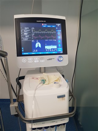
One detail ties these back to the connected device this series is about: many flow meters speak in pulses, one edge per fixed volume, and a totaliser downstream counts them into a running sum. That interface is robust and a little dumb, and it hides the instantaneous rate a control loop may want, so a design that needs both the flow now and the volume so far either picks a meter with a digital readout like the SFM3019 or pairs the pulse train with its own timing. The meter quietly sets what the firmware upstream can even ask for.
So the selection runs: what the fluid is, conductive or not, clean or not, liquid or gas; what may touch it; what the pipe allows; and only then which footprint to read. The four articles under this one walk the branches: the liquid-flow principles in detail, the SFM3019 as the worked example of gas mass flow, the non-contact level toolbox, and the ultrasonic mounting rules that keep a good sensor from giving bad answers. None of the four repeats this overview; each goes down into the detail the page above only points at. Flow first, level second, and in both the same discipline applies: name the assumption the number rides on, then check that the fluid in the pipe or the tank keeps it.
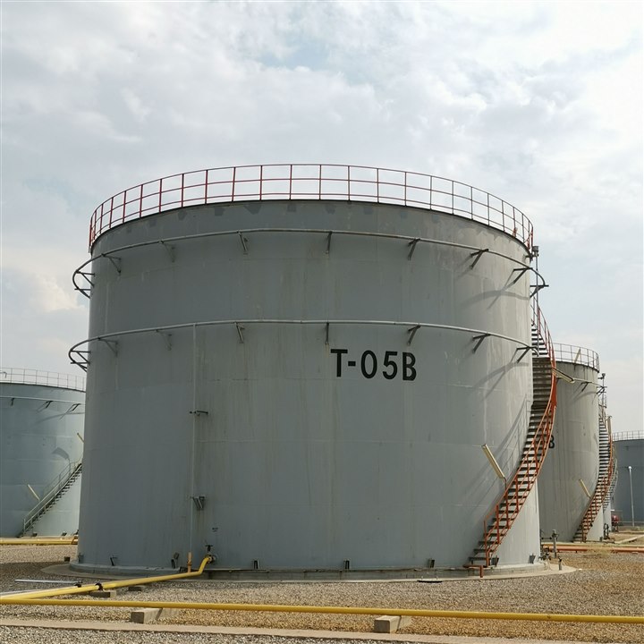
The fluid does not read the datasheet. It keeps its own properties, and the meter that agrees with them is the one that stays honest after the commissioning engineer drives away.






