Vishay 40 V TrenchFET Gen IV Standard-Level MOSFETs for Motor Control
Vishay has introduced four 40 V TrenchFET Gen IV standard-level N-channel MOSFETs for motor-control power stages: SIR5402DP, SIR5404DP, SIR5406DP, and SIR5408DP. The devices combine a 2.5 V minimum gate-source threshold specification with a low Miller-charge ratio, giving designers a focused option where electrical noise on the gate can otherwise cause an unintended switching event.
Contents
- Released devices and key data
- Why threshold voltage and Miller ratio matter
- Selecting the device within the four-part range
- Package and board-level checks
- Related information
Released Devices and Key Data
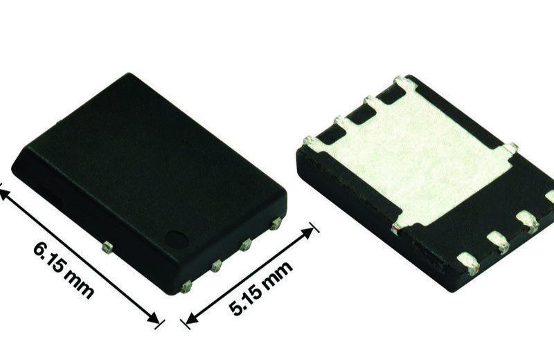
Announced on July 7, 2026, the family uses Vishay's 6.15 mm by 5.15 mm PowerPAK SO-8 single package. Each device is rated for 40 V drain-source voltage and plus or minus 20 V gate-source voltage. Vishay positions the series for BLDC motor stages, power tools, drones, synchronous rectification, and DC/DC conversion where a 10 V gate-drive environment is available.
| Part number | Typical RDS(on) at 10 V | Typical total gate charge | Typical Qgd/Qgs |
|---|---|---|---|
| SIR5402DP | 0.9 mOhm | 82 nC | 0.69 |
| SIR5404DP | 1.55 mOhm | 61.5 nC | 0.73 |
| SIR5406DP | 1.9 mOhm | 44 nC | 0.75 |
| SIR5408DP | 2.5 mOhm | 32.6 nC | 0.71 |
The four parts create a usable conduction-loss and gate-drive tradeoff inside one package family. The values above are typical values from Vishay's release; verify the applicable datasheet limits, temperature conditions, and board thermal path before fixing a design choice.
Why Threshold Voltage and Miller Ratio Matter
In a switching motor stage, drain-voltage movement can couple through the MOSFET capacitances to the gate. If that transient lifts the gate voltage toward threshold while the device should be off, it can create a false turn-on risk. Vishay specifies a 2.5 V minimum gate-source threshold for these standard-level devices and Qgd/Qgs ratios below one, with the listed devices ranging from 0.69 to 0.75.
That does not remove the need for a sound gate-drive design. Review the gate-driver sink impedance, common-source inductance, turn-off resistor, negative transient margin, and the switching waveform at the actual board layout. The released family provides a starting point for designs that need both low on-resistance and a deliberate gate-noise review.
Selecting the Device Within the Four-Part Range
Start with the conduction-loss target and the available gate-drive current. SIR5402DP offers the lowest typical on-resistance in the group and the highest listed total gate charge. Moving toward SIR5408DP reduces the listed gate charge while increasing typical on-resistance. SIR5404DP and SIR5406DP provide intermediate steps when the thermal budget and switching-loss budget need to be balanced.
- Confirm that the gate driver provides the intended 10 V drive condition used for the stated RDS(on) values.
- Compare conduction loss using the worst-case RDS(on) at the relevant junction temperature, not only the typical room-temperature figure.
- Calculate switching loss with the selected driver's source and sink current, the actual bus voltage, and the measured switching frequency.
- Check avalanche, current, thermal, and safe-operating-area requirements against the part-specific datasheet for the final motor or converter topology.
Package and Board-Level Checks
The PowerPAK SO-8 single package keeps the family in a common 6.15 mm by 5.15 mm footprint. For a low-resistance MOSFET, copper spreading and the current-return path are central to the final result. Keep the driver loop short, place local decoupling close to the half-bridge or switching node, and separate sensitive gate-return routing from high di/dt power paths where the layout permits.
Because the article covers a new series release, it should not be used as a substitute for device-level qualification. Confirm the final part number, thermal design, transient behavior, and application requirements with the current Vishay datasheet before release to production.
Related Information
- Choosing MOSFET Parts for Switching and Power Circuits
- Choosing LDO and DC DC Parts for Each Power Rail
- Doing Solid Power Conversion for a Connected Device
Source: Vishay Intertechnology standard-level 40 V MOSFET release.