Free Shipping Over$200

- Products
- Marking
- Alternative

IS25LP256E-JLLA3 as a 256 Megabit SPI Flash
IS25LP256E-JLLA3 as a 256 Megabit SPI Flash
The IS25LP256E-JLLA3 is a 256-megabit serial NOR flash, which gives a host 32 megabytes of nonvolatile storage through a pin-efficient SPI interface. The exact device belongs to the 3 V IS25LP family, operates from 2.3 to 3.6 V, and uses an automotive A3 temperature grade from -40 to +125 degrees C. Its JLLA3 ordering suffix identifies the standard device option in a RoHS-compliant 8-contact WSON package measuring 8 x 6 mm.
That combination suits boot images, controller firmware, graphics, voice assets, FPGA configuration data and recovery content that are too large for a small internal flash but do not need managed NAND. Density alone is an incomplete selection rule. At 32 MB the design must choose three- or four-byte addressing, match the host's quad-enable and reset behavior, budget erase and update space, and prove signal integrity at the selected clock and temperature corners.
The family supports standard SPI, dual and quad transfers, QPI, single-transfer-rate reads up to 133 MHz for the 3 V version, and double-transfer-rate operation up to 80 MHz. Those headline modes are useful only when controller commands, dummy cycles, drive strength, board routing and software state agree. A reliable design therefore treats the flash as a system component spanning schematic, layout, boot code, field update, production programming and approved-source control.
Decode the Full IS25LP256E-JLLA3 Order Code
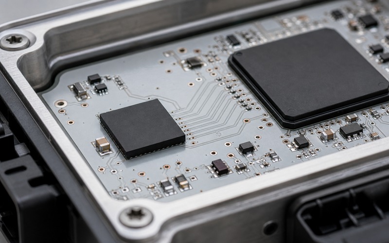
IS25LP identifies a 2.3-to-3.6 V serial NOR family with QPI capability, 256 identifies the 256Mbit density, and E identifies the die revision. After the hyphen, J is the standard option, the first L selects the 8-contact 8 x 6 mm WSON, the second L identifies the compliant package content, and A3 selects the automotive temperature range. The full suffix must appear in the BOM, footprint record, programming setup and incoming inspection criteria.
The A3 grade is specified from -40 to +125 degrees C and the ordering note states that it meets AEC-Q100 requirements with PPAP. That does not make every board automatically qualified for an automotive environment. The controller, power rail, solder process, enclosure, data-retention target and system validation must be reviewed at the same temperature and reliability level.
Convert 256 Mbit into a Real 32 MB Memory Map
A density of 256Mbit equals 33,554,432 bytes, or 32 MiB in a binary address map. Reserve space for image headers, signatures, version records, calibration blocks, factory identity, recovery metadata and erase alignment before deciding how many executable or data images fit. A nominal 16 MB application does not leave a clean 16 MB second slot once authentication, rollback and wear-managed records are included.
Write the map as explicit start and end addresses and assign ownership to the boot loader, main application, updater and production station. Keep immutable recovery content away from frequently changed settings. If graphics or language assets are updated independently from code, give them separate version and integrity records so a partial asset transfer cannot invalidate an otherwise bootable system.
Choose Three-Byte or Four-Byte Addressing Deliberately
Three address bytes cover only 16 MiB, half of this device. The upper half requires four-byte commands or entry into a four-byte address mode, depending on the host controller and command path. The boot ROM may use one method while the operating software uses another, so both stages must agree on how addresses above 0x00FFFFFF are reached.
Test reads and erases on both sides of the 16 MiB boundary. A driver can appear correct for months when all released images live below that boundary, then fail after an update grows into the upper half. Reset, deep power-down and handoff between boot stages may also change volatile address-mode state, which must be restored before the next high-address access.
Select SPI, Quad I/O or QPI for the Workload
The part supports ordinary single-bit SPI, dual transfers, quad transfers and QPI, where instructions and addresses can also use four data lines. Single SPI is simple for identification and recovery. Quad I/O improves sustained reads without adding a wide parallel bus. QPI can reduce instruction overhead, but it adds software state that every reset and recovery path must understand.
Choose the least complex mode that meets boot-time and execution needs. A controller loading one 2 MB image once at startup may not benefit from the most aggressive mode. A processor fetching code or large assets repeatedly may benefit, provided cache behavior and random-access command overhead are included in the measurement. Keep a conservative single-SPI escape path for diagnosis and recovery.
Treat 133 MHz and 80 MHz DTR as System Limits
For the 3 V IS25LP256E family, fast single-transfer-rate reads are specified up to 133 MHz; double-transfer-rate modes are specified up to 80 MHz. Normal read is listed at 50 MHz. The effective throughput also depends on bus width, command overhead, dummy cycles, chip-select gaps and the host's receive timing. A frequency printed in a feature list is not a guaranteed application bandwidth.
Start bring-up at a low clock and read identification, SFDP data and known patterns. Then test long and short reads across page, sector, 16 MiB and wrap boundaries while sweeping the intended voltage and temperature range. Record which dummy-cycle setting, drive strength and controller sampling point were used, because a later firmware change can otherwise remove the margin established during hardware validation.
Use SFDP Instead of Hard-Coding Every Assumption
Serial Flash Discoverable Parameters provide a machine-readable description of important capabilities and timing. A robust driver can use SFDP to confirm density, erase instructions and supported operating modes rather than relying only on a model table compiled into software. The exact device identity should still be checked so an unexpected family or revision is not silently accepted.
Store a validated parameter snapshot with the released software and compare it during qualification of a second source. Controller boot ROMs vary in the SFDP revisions and fields they understand. If the ROM has fixed assumptions, verify the exact reset state, quad-enable location, dummy-cycle default and address method that the ROM uses before the application driver takes control.
Design the Six High-Speed Signals as One Interface
A quad connection uses clock, chip select and four bidirectional data lines. Route them over a continuous reference plane, keep stubs short, avoid unnecessary vias and place the flash close enough to the host that trace delay and skew remain controlled. The clock path deserves particular attention because its edges can be much faster than the nominal cycle period suggests.
Series damping near the driver can help on some boards, but values should come from simulation or measurement rather than habit. Check loading from probes, test points and alternate footprints. At cold and hot corners, measure read margin with production boards and the final processor I/O drive setting. A successful bench read at room temperature is an initial observation, not signal-integrity qualification.
Hold Power and Reset States in a Known Condition
The IS25LP device uses a 2.3-to-3.6 V supply. Place local ceramic decoupling close to the WSON power contacts and keep chip select inactive during rail transitions. Confirm that the processor does not back-power the unpowered flash through data or clock pins. Brownout thresholds and rail sequencing must prevent a new program or erase command when the supply is no longer valid.
The family provides software and hardware reset mechanisms. Define which mechanism the board actually connects and which sequence each software stage uses. Do not reset during an active program or erase operation. Poll status first, and after an abnormal restart restore address mode, I/O mode, dummy cycles, drive strength and protection state before trusting data from the array.
Respect Page and Erase Geometry
The standard organization programs from 1 to 256 bytes per page and erases 4 KB sectors or 32 KB and 64 KB blocks, as well as the full array. The exact J standard option should be treated as the standard 256-byte-page geometry. A program command that crosses a page boundary can wrap or write an unintended location depending on device behavior, so the driver must split every transfer explicitly.
Small mutable records should use an append-only or rotating design instead of erasing a sector for every change. Large image updates can use 64 KB blocks for speed while preserving 4 KB sectors for metadata. Always poll the write-in-progress state, apply a bounded timeout based on guaranteed limits, and read back the programmed range before making it active.
Build a Power-Fail-Safe Update Scheme
A field update should leave at least one verified boot path while new content is received. With 32 MB, dual image slots may be practical, but the memory map must include signatures, rollback counters, configuration migration and scratch space. Write the inactive image first, verify its complete cryptographic or integrity record, then change a small activation record using redundant copies.
Power loss during program or erase makes the target region uncertain. On restart, inspect both activation records and image integrity before choosing a slot. Do not erase the previous valid image until the new one has survived a cold boot and the product's acceptance checks. This sequence protects against interrupted transfers, weak supplies and unexpected resets without assuming that one capacitor can finish every operation.
Plan Endurance and Retention by Data Class
The family specification states more than 100,000 erase/program cycles and more than 20 years of data retention. Those values do not remove the need for a write-rate calculation. A log, counter or frequently changed setting concentrated in one 4 KB sector can reach its cycle budget long before the firmware image, which may be written only a few times.
Separate code, factory constants, service logs and user settings. Rotate high-write records across several sectors and include sequence numbers plus integrity checks. For long-lived hot environments, review retention against the actual temperature profile and maintenance policy. A periodic verified refresh may be appropriate for selected data, but it must preserve a known-good copy during the refresh operation.
Use Protection Features with a Defined Policy
The device includes software and hardware write protection, sector or block protection, top or bottom protection and power-supply lock protection. It also provides four dedicated 256-byte security areas with user-lockable bits. These features can protect a recovery loader, factory calibration or immutable identity from accidental erase and program operations.
Protection settings are part of the released configuration, not a late production checkbox. Test an operation that should be rejected, record the expected status, and define how an authorized service update temporarily changes and restores protection. Memory locking does not replace signed images, secure key storage or access control when the threat model includes deliberate modification.
Account for Active, Standby and Deep-Power Current
The feature specification lists 7 mA active-read current, 10 microamps standby current and 1 microamp deep-power-down current. Active current matters during sustained boot or asset loading, while the difference between standby and deep power-down matters in a battery-backed controller that sleeps for long intervals. Board-level current also includes pull resistors, translators and host-pin leakage.
Define one owner for entry to and release from deep power-down. Boot code, application code, diagnostics and the update service must not disagree about the device state. Measure wake latency and first-read validity, and test a reset while the device is asleep. The recovery sequence should return to a simple SPI state before applying higher-speed modes.
Build the Exact 8 x 6 mm WSON Footprint
The L package is an 8-contact WSON measuring 8 x 6 mm, with four hidden contacts along each long side. Build the land pattern, solder mask, paste apertures and pin-one mark from the exact ISSI drawing. Do not substitute a generic DFN or WSON footprint merely because the body outline and contact count appear similar.
The hidden joints require a controlled assembly process. Keep copper escape symmetric where possible, avoid paste volumes that float or rotate the body, and inspect first articles with suitable optical and X-ray methods. The local decoupling component should remain close without blocking inspection or rework access. Package and stencil revisions belong in the production record.
Make Production Programming Traceable
The programming definition should state the full order code, expected device identity, SFDP check, address mode, erase map, image version, hash and protection settings. Read identity before erasing. Program only the intended regions, read them back through the same interface used by the product, and verify immutable and mutable areas separately.
After programming, remove power fully and perform a cold boot at the conservative interface setting. Then exercise the released high-speed mode. Record image, tool, adapter and fixture revisions against the board record. This evidence helps distinguish an image problem, a wrong flash option, a solder defect and a marginal high-speed interface during later failure analysis.
Qualify Substitutes Beyond Density and Pinout
A candidate replacement must match supply, temperature grade, package drawing, pin functions, reset state, quad-enable behavior, three- and four-byte addressing, SFDP response, dummy cycles, erase commands, page size, protection scheme, identification and power modes. A 256Mbit QSPI label and an 8-pin outline are only the beginning of the comparison.
Run the same boot, random-read, high-address, program, erase, suspend, protection, deep-power-down, brownout and recovery tests on every approved source. Repeat timing at voltage and temperature corners. If software branches by manufacturer identity, test both paths in production programming and field update tools so the second source is genuinely deployable rather than present only in a purchasing table.
Final Engineering Checklist
Confirm 32 MB capacity and slot layout, 2.3-to-3.6 V compatibility, A3 temperature requirement, 8 x 6 mm WSON footprint, three- or four-byte address strategy, selected SPI or QPI mode, frequency, dummy cycles, drive strength, page and erase geometry, protection policy, deep-power state and power-fail recovery. Freeze these choices in hardware and software release records.
On production-intent boards, verify identification, SFDP, lower and upper address ranges, page boundaries, every erase size used by software, sustained reads, cold and hot operation, interrupted updates, reset, protection, sleep and cold boot. Approve the exact order code only after the same programming and recovery flow used in manufacturing has passed these checks.