Free Shipping Over$200

- Products
- Marking
- Alternative

Why a Pin Compatible AI Substitute Can Still Fail in the Field
Why a Pin Compatible AI Substitute Can Still Fail in the Field
A pin-compatible AI processor can pass a short bench test and still fail months later in deployed equipment. The package lands on the existing pads, the board boots, and a demonstration model runs. Those results prove that the substitution is possible under one set of conditions. They do not prove that the new device has the same electrical margins, startup behavior, memory tolerance, thermal response or software behavior across the product's operating range.
Pin compatibility describes a physical and logical boundary. It says that corresponding package terminals are intended to serve compatible functions. It does not guarantee equal leakage, drive strength, power-rail sequence, clock sensitivity, memory training, package warpage, thermal resistance, silicon errata or accelerator output. Any one of those differences can stay hidden during an office test and appear after temperature cycling, a supply dip, a camera burst or a long inference workload.
A reliable substitution therefore starts with a difference review and ends with product-level evidence. Engineers need to compare the exact orderable codes, map every changed limit to the real board, rebuild the software stack, test production corners and define what field behavior will be monitored. Purchasing approval should follow that technical result rather than treat a matching footprint as the result itself.
Treat the Pin Map as the Beginning of the Review
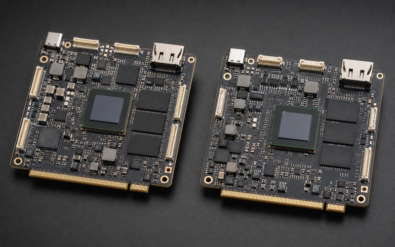
Compare the complete pin tables, ball maps and package drawings for the released device and the proposed substitute. Check power, ground, no-connect, reserved, test, strap and analog pins as carefully as the named interfaces. A ball marked reserved on one device may require a defined state on another. A no-connect pad on the board can become a startup input, while an internal pull resistor can move a mode strap close to its threshold.
Review package dimensions beyond body width and ball pitch. Substrate thickness, stand-off height, corner-ball pattern, package coplanarity and the location of the exposed thermal path affect assembly and board strain. Confirm the paste process, reflow profile, inspection method and underfill policy. A package that fits the land pattern can still produce a different solder-joint reliability result after vibration or thermal cycling.
Compare Electrical Limits, Not Typical Values
Build a side-by-side table from the latest data for every rail and interface used by the board. Include absolute maximum ratings, recommended operating ranges, input thresholds, output levels, leakage, clamp current, drive strength, power-domain tolerance and behavior when a neighboring rail is off. Typical values help explain normal operation, but qualification needs guaranteed limits across process, voltage and temperature.
Pay attention to mixed-voltage pins and apparently unused interfaces. A substitute may place a protection diode, pull device or fail-safe buffer on a terminal that behaved differently in the original part. The result can be back-powering through an external device, excessive standby current or a slow rail that never reaches a valid off state. Measure current paths during power-up, shutdown, sleep and fault recovery instead of checking steady-state current alone.
Recheck Every Power Rail and Sequence
AI processors create steep load steps as compute blocks, memory controllers and high-speed interfaces change state. Compare the substitute's rail count, nominal voltage, tolerance, ramp-rate limits, sequence rules, reset timing and current demand in each workload. A regulator sized for the original average current may hit current limit when the substitute wakes a larger block or uses a different clock transition.
Probe the rails at the processor balls or the nearest practical test points. Exercise cold start, warm restart, brownout, rapid input cycling, sleep entry, sleep exit and watchdog recovery. Record droop, overshoot, settling and reset release. Repeat with realistic cable loss and the lowest specified input supply. Field failures often come from a brief sequence violation that a bench supply and a slow manual power cycle never create.
Prove Boot and Memory Margins Again
A substitute can use the same memory type while requiring different training firmware, termination, drive settings or layout margin. Rebuild the boot chain with the supported initialization code for the exact silicon revision. Check boot ROM behavior, strap sampling, flash mode, secure-boot keys, recovery path and fallback image. An old binary that happens to boot once is weak evidence for a production release.
Stress memory with the real topology and population. Run repeated cold boots at temperature limits, high-bandwidth transfers, refresh-sensitive patterns and long inference workloads that compete for memory. Look for corrected errors, training retries, intermittent boot delay and data corruption. If the original board was already close to its timing margin, a small change in controller or package delay can turn a laboratory success into a field return.
Measure Clocks and High-Speed Interfaces Under Load
Compare clock input requirements, oscillator loading, spread-spectrum support, jitter tolerance and phase-locked-loop lock behavior. Verify that the existing crystal or oscillator network meets the substitute's guaranteed limits across temperature and component tolerance. A device may start with a clean laboratory clock yet lose lock when a fan, radio or motor injects noise into the board.
Retest PCIe, USB, Ethernet, MIPI and other fast links with the substitute installed. Use the correct compliance method, realistic cables and the product enclosure. Check equalization, lane polarity options, reference-clock mode, reset timing and error counters. Passing one short transfer does not reveal marginal eye opening, receiver adaptation or a burst of errors after the processor and memory reach full temperature.
Recalculate Thermal and Mechanical Margin
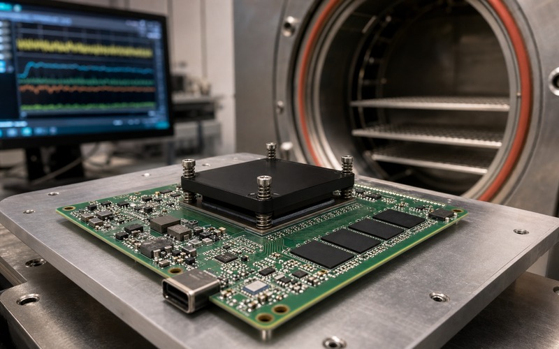
Equal package size does not mean equal junction temperature. Compare power in the actual model workload, thermal resistance definitions, sensor location, throttle thresholds, maximum junction temperature and the way heat spreads through the package. Validate the existing heat sink, interface material, mounting pressure, airflow and enclosure orientation with the substitute. Read both on-die telemetry and an independent measurement where practical.
Run sustained workloads long enough for the enclosure and surrounding components to reach equilibrium. Include blocked vents, fan aging and high ambient temperature if the product can encounter them. Watch for clock throttling, memory errors, regulator heating and timing drift. Mechanical checks should cover heat-spreader contact, board deflection, package keep-out and repeated thermal cycles, since an altered package stack can change stress even when the outline is identical.
Rebuild the Software and Accelerator Path
The substitute needs a supported board package, boot firmware, operating-system branch, drivers, compiler, model converter and runtime combination. Rebuild from a controlled environment instead of carrying forward an image without understanding its dependencies. Compare device-tree settings, power states, interrupt routing, IOMMU behavior, memory allocation and security configuration. Record every deliberate difference from the released software baseline.
Check model outputs, not merely application launch. Run representative networks through preprocessing, quantization, accelerator execution and postprocessing, then compare accuracy and numerical tolerance against the approved result. Different compiler versions or accelerator revisions can change operator placement, precision and fallback behavior. A model can appear fast and stable while producing a small output shift that matters to a threshold-based product decision.
Exercise Environmental and Workload Corners
Create a test matrix from the conditions the product can actually see: minimum and maximum supply, cold and hot start, humidity where relevant, vibration, electromagnetic disturbance, network bursts, camera changes, storage pressure and concurrent peripheral activity. Combine conditions that interact. Maximum inference load at room temperature is less revealing than a cold boot on a weak supply followed by a rapid transition into full memory and interface traffic.
Use enough units and cycles to expose intermittent behavior. One engineering sample can hide process variation, package variation and assembly spread. Include samples from more than one date or manufacturing lot when possible, and compare them with released units on the same fixtures. Log resets, corrected errors, thermal events, link retraining, watchdogs and output anomalies so a rare failure has evidence behind it.
Separate Qualification From a Quick Functional Check
Define acceptance criteria before testing. The plan should state which functions, limits, temperatures, workloads, durations and sample counts are required, who reviews deviations, and which changes need customer or regulatory approval. Reuse prior evidence only when the hardware, software and operating condition are genuinely equivalent. A substitution can reduce some work, but the skipped work needs a technical reason.
Use staged gates. Schematic and data comparison should precede board power-up. Electrical characterization should precede environmental stress. Software accuracy and recovery testing should precede a controlled production build. The production build should include assembly inspection, programming, functional test and traceability. This sequence catches inexpensive problems early while preserving evidence for the harder product-level decision.
Control Production Release and Field Feedback
Release the substitute as a controlled configuration with its own approved code, software baseline, test limits and manufacturing records. Do not mix old and new processors under one ambiguous material description. Manufacturing needs a reliable way to identify the fitted device, select the correct program image and apply any revised test thresholds. Service teams need the same distinction when they diagnose returned units.
Watch the first controlled builds and early field population for signals predicted by the risk review. Compare boot time, reset causes, thermal telemetry, interface errors, model output checks and return symptoms with the released device. Define a stop rule and a containment path before volume increases. A pin-compatible substitute is ready when the product evidence supports it across real corners, not when the package can be soldered onto the board.
Preserve enough diagnostic detail to separate the processor change from unrelated field noise. Record the fitted revision, software build, reset register, recent supply events, maximum temperature, memory error state and interface counters before a service action clears them. Link those records to manufacturing lot and board revision. Without that traceability, several weak signals can be dismissed as unrelated returns even when they share one substitution mechanism.
Use a Product-Level Substitution Checklist
Before approval, confirm the exact orderable code, package drawing, ball map, reserved-pin rules, electrical limits, rail sequence, reset timing, clock requirements, memory initialization, high-speed interface margin, thermal path, software support, model accuracy, security functions and manufacturing test. Record the source and revision of each item so later changes can be reviewed against a known baseline.
Close every deviation with one of three outcomes: evidence that the existing design covers it, a controlled hardware or software change, or a documented product restriction. Keep unresolved items out of production release. This approach turns pin compatibility into a useful screening condition while keeping the approval tied to how the complete AI product behaves in manufacture and in the field.
Repeat the review when the substitute receives a die revision, package change, new compiler branch or changed manufacturing site. The original approval applies to the tested configuration and evidence set; it is not a permanent waiver for every later variant. A short, disciplined change review protects the qualification investment and prevents a silent revision from reopening the same field risk.
Related information
- 2026.07.14 MX25V1006FZUI as a Small Density SPI Flash
- 2026.07.14 W25N01GVZEIG as a 1 Gigabit SPI NAND Flash
- 2026.07.14 W25Q64JVZEIM as a 64 Megabit SPI NOR Flash