 Free Shipping Over$200

- Products
- Marking
- Alternative

Fitting Robotics and Motion AI with Drive and Feedback
When an AI plans a motion, something else has to make the motor turn and then report back what the motor did. That is the job of the drive and feedback parts, and they sit between the model and the moving world. A command goes out, a driver turns it into the current a motor needs, the motor moves, and a feedback sensor measures where things ended up so the model can plan the next move.
The parts split along that loop. The drivers, stepper or DC, turn a low power command into the power a motor takes. The feedback sensors, angle and current, measure what the motor did. And because a motor driver is electrically loud, a real part of the work is keeping its noise out of the quiet board that runs the model. Each of these is settled in hardware, around the motor, before the control loop can be trusted.
The loop the AI plans inside
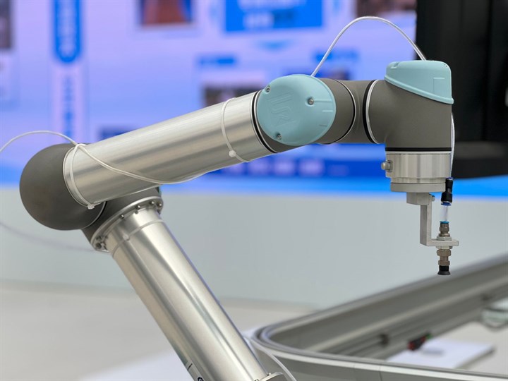
A model that controls motion does not move anything by itself. It produces a target, a position to reach or a speed to hold, and hands it to a control loop that turns the target into motor current and watches the result. The loop runs far faster than the model thinks, correcting the motor many times over for every decision the model makes.
That division decides what each part has to do. The model can be slow and clever. The loop under it has to be fast and dependable, since it is the part that keeps the motor on target between the model's decisions. The drive and feedback parts are the loop's hands and eyes, and the model is only as good as what they let it command and sense.
The gap between the two rates is wide. A model might settle a new target a few times a second, while the loop beneath it corrects the motor thousands of times in that same second, each correction far too fast and too frequent for the model to make. That split is the point: the loop handles the fast, repeating work of holding the motor on target, and the model is freed to do the slow work of deciding where the target should be.
Driving a stepper without losing steps
A stepper motor moves in fixed steps, which makes it easy to position without feedback, since counting steps counts position. The catch is that a stepper holds position only while the driver feeds it enough current, and pushed too hard or too fast it can skip a step and lose its place with nothing to show for it.
The TMC2209 drives a stepper quietly in a robot joint. It microsteps the motor for smooth motion and runs it with a current control that keeps the audible whine down, which matters on a device that works near people. It carries the current the motor needs, guards against overcurrent and overheating, and takes step and direction signals from the controller. The quiet drive and the smooth microstepping suit a joint that moves where it can be heard.
A stepper driven this way is open loop, and that holds up until it does not.
A plainer stepper driver for a motion stage
Where the motion is on a machine rather than beside a person, a plainer stepper driver does the job. The DRV8825 drives a stepper on a motion stage, handling a higher voltage and current per coil than a small joint driver, with microstepping set by a few pins and the current limit set by a trimmer. It fits a linear stage or a gantry where the load is larger and the noise of the drive is not a concern.
The choice between a quiet driver and a plain one is set by where the motion happens and how large the load is. A quiet driver earns its price beside people, and a plain one is enough on a machine in a cabinet.
Microstepping is a trade on either driver. More microsteps smooth the motion and quiet it but ask the driver and controller to step faster for the same speed, and past a point the extra steps buy little resolution the motor can use under load. The setting is picked for the smoothness the application needs, not the highest number the driver offers.
Turning a small DC motor both ways
Not every motion wants a stepper. A small DC motor is cheaper and simpler when exact position is not the point, for a wheel, a fan, or a gripper that has to open and close. Driving it means switching its current on, off, and into reverse, which a controller cannot do on its own pins.
The TB6612FNG drives a small DC motor, a dual H bridge that runs two DC motors forward and back from a controller's logic signals, with the current a small robot's motors take. It fits a wheeled robot or any device with a couple of small motors that need direction and speed but not precise position.
Speed and direction come out of the same switching the driver does for everything. Pulse width modulation sets the average voltage and so the speed, reversing swaps which way the H bridge connects the motor, and braking shorts the motor's terminals so its own generated voltage slows it. A small robot gets its direction, its speed and its stop from those few switch states.
Telling the AI where the shaft is
A motor that has to land on an exact angle, a servo joint or a steering axis, needs to measure where its shaft sits, not where it was told to go. A magnetic angle sensor does that without touching the shaft.
The AS5047P reports a servo motor's angle from a small magnet on the end of the shaft. It reads the absolute angle through a full turn and sends it to the controller fast enough to close a motion loop. Mounted over the shaft magnet, it gives the loop the true angle every cycle, which is what lets a controller hold a position against a load rather than hope the motor reached it.
Two things decide whether the angle reading can be trusted. The sensor has to be absolute, reporting the true angle the moment it powers up rather than counting from where it started, so a joint knows its position after a reset without a homing move. And the magnet has to sit centered over the sensor within a tolerance, since a magnet off center or too far away reads a distorted angle the loop will faithfully act on. The mounting is part of the measurement.
Reading the current to feel the load
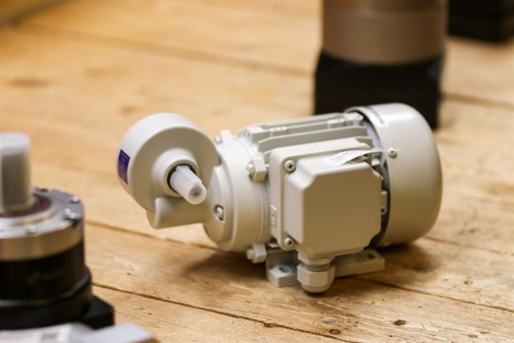
The current a motor pulls is a direct read on how hard it is working, and a control loop uses it to limit torque, catch a stall, and run the motor efficiently. Measuring it means sensing a small voltage across a shunt resistor in the motor's current path, often while that point swings up and down as the driver switches.
The INA240 senses the phase current in motor control. It is built to read the shunt voltage even as the common mode voltage swings with the switching, which is what makes it usable in a motor drive rather than only in a quiet bench circuit. It hands the controller a clean current reading to close the torque loop and to catch a motor that has stalled or jammed.
Where the shunt sits changes what the reading shows. A shunt in line with the motor phase reads the true motor current but floats at the switching voltage, the hard case the amplifier has to handle. A shunt in the ground return is easier to read but sees the current only while the low side switch is on, so it misses part of the picture. The placement is chosen for what the loop needs to see against what the amplifier can take.
How the loop turns error into current
Between the command and the motor sits the law that turns the gap into a correction. The loop takes the target, subtracts what the feedback measured, and acts on the difference, the error. A loop that reacts to the error alone is jumpy, one that also sums the error over time erases the steady offset a load leaves, and one that watches how fast the error changes damps the overshoot. Those three together are the proportional, integral and derivative terms a motion loop is built from, tuned to the motor and the load it drives.
Tuning is where this gets concrete. Too much proportional gain and the motor oscillates around the target, too little and it drags toward it and never settles on it. Too much integral and it overshoots and rings, too little and it settles short under load. The gains are set against the motor's inertia and the stiffness of what it drives, and a loop tuned for a light arm shakes a heavy one. There is no single set of numbers, which is the reason tuning is part of the design and not a default.
The correction has to reach the motor in a form it takes. A driver does not set current directly. It switches the supply on and off fast and lets the average set the current, which is pulse width modulation. The loop sets the duty cycle, the fraction of each period the supply is connected, and the motor's inductance smooths the pulses into a steady current. The switching frequency is picked high enough to stay smooth and quiet and low enough to keep the driver from burning power in every switch.
A brushless motor adds commutation on top. Its windings have to be energized in the right order as the shaft turns, so the loop has to know the rotor angle to drive it at all, which ties the angle feedback to the drive rather than leaving it an extra. A brushed DC motor and a stepper handle commutation mechanically or by step pattern, part of why they are simpler to drive, and a brushless motor trades that simplicity for efficiency and smoothness.
The model has one more job in the loop, shaping the path the target follows. A target that jumps makes the motor lurch and overshoot, while a target ramped smoothly, speeding up and slowing within what the motor can do, lets the loop follow without fighting. This trajectory planning sits with the model, which knows where the motion is headed, and it turns a string of positions into motion that does not jerk at every step.
The parts for this are light, and the work is in getting the gains right for the motor and the load.
Open loop, closed loop, and what the AI can trust
The deepest decision under all of this is whether the loop is open or closed, because it sets what the AI is allowed to believe. An open loop motor, a stepper counting its own steps, assumes it reached every position it was commanded, and much of the time it did. The trouble is the time it did not. A stepper that hits a jam or gets pushed past its torque skips steps and keeps counting as if nothing happened, so the controller's idea of position drifts away from the truth with no error to mark it, and a robot arm that believes it is in one place while it sits in another is a safety problem rather than a glitch. Closing the loop fixes this by measuring the real result, the angle from a sensor on the shaft and the current the motor draws, and feeding it back so the controller corrects to the truth every cycle. The angle says where the shaft sits. The current says how hard the motor is working and whether it has stopped moving. With both, the controller can hold a position against a disturbance, ease off when the load spikes, and tell the model that a move failed instead of reporting a success that never happened. The cost is the feedback sensors, the wiring out to them, and a loop fast enough to act on what they report. Whether to pay it comes down to what a wrong position costs: a printer that skips a few steps wastes a print, and a robot that loses its place can break itself or injure someone, so the second closes the loop whatever the price. The model on top is only as trustworthy as the loop beneath it, since a model planning from a position that is quietly wrong gives confident commands that miss.
What the loop can hold to is capped by the feedback it gets. An angle sensor with coarse resolution lets the shaft sit a little off before the loop even sees the error, so the motion hunts around the target instead of landing on it. A sensor that reports slowly lets the error grow between readings, which forces the loop to react gently to stay stable and leaves it soft against a sudden load. The resolution and the update rate of the feedback set the ceiling on how tight and how stiff the loop can be, so the sensor is chosen for the loop and not for the angle alone.
A robot that can damage itself or its surroundings closes the loop for that reason.
Keeping the motor's noise off the AI board
A motor driver switches large currents fast, which makes it one of the loudest electrical neighbors a circuit can have. The switching couples noise onto the supply and the ground and radiates it into nearby traces, and the AI board, with its fast low voltage logic and its sensitive sensor inputs, is the kind of circuit that noise upsets.
Keeping that noise away from the AI board is a design job of its own. The control signals crossing from the quiet side to the motor side can pass through digital isolators that carry the logic while breaking the noisy ground connection. The motor supply runs on its own path back to the source rather than sharing one with the logic, and the layout puts distance and a clean ground between the switching and the sensitive parts.
The current sensing sits in the middle of this fight, since the shunt it reads lives on the switching node where the noise is worst, which is the reason a motor current amplifier is built to hold its reading steady while the voltage around it swings. Shielding helps where the noise radiates, a ground plane under the fast traces and a can over the worst of it, and the larger gains come from keeping the noisy return currents out of the quiet ground in the first place.
Done well, the motor drives hard while the model reads its sensors cleanly. Done poorly, the device resets or misreads each time the motor moves.
Powering the motor without starving the logic
A motor pulls far more current than the logic that commands it, and it pulls in bursts, when it starts, reverses, or fights a load. That demand lands on the power supply, and a rail sized for the quiet logic sags when the motor lunges, which can reset the controller at the worst moment.
So the motor gets its own supply path, sized for the peak it draws and not the average, with bulk capacitance close to the driver to feed the surge the supply cannot answer fast enough. The logic runs from its own regulated rail, taken off ahead of the motor's draw so the motor's sag does not reach it. The two share a ground, and where they join is chosen so the motor's return current does not run through the logic's ground.
Regenerative energy is the part that catches a first design. A motor driven to slow down acts as a generator and pushes current back into the supply, lifting the rail, and a driver or a clamp has to absorb that energy rather than let the rail climb until something downstream fails.
The driver's own heat is part of this. Carrying motor current through its switches loses power as heat, more at higher current, and a driver that overheats throttles back or shuts off mid move. So it gets the copper, the thermal pad and sometimes the airflow to shed that heat at the current the motor draws, sized for the worst case and not the catalog average.
The timing the loop runs at
A control loop is only as good as how often it runs and how quickly it reacts. The feedback has to be read, the correction worked out, and the new current sent to the motor, many times a second, and the rate that holds a motor steady is far higher than the rate at which the model makes decisions.
This splits the timing into two layers. The fast loop, reading the angle and current and driving the motor, runs on a dedicated controller close to the motor, where its timing stays tight and predictable. The model runs above it at its own slower pace, sending targets down and reading results back. Putting the fast loop on the same processor as the model, where the model's heavy and variable timing can stall it, is how a motor that should hold steady ends up juddering.
Jitter matters as much as rate. A loop that runs every millisecond but sometimes late corrects on stale information, and the motion shows it as roughness even when the average rate looks fine. So the fast loop wants a controller that can promise when it runs, a timer or interrupt that fires on schedule, since steady motion needs the loop to run on time more than it needs the loop to run fast.
The two rates are designed apart on purpose, and joining them is a false economy that the motion shows.
The safety the model is not trusted with
A model that drives motion can be wrong, and a wrong command to a motor moves real mass. So the parts that keep a machine safe are built below the model, in hardware and simple logic that does not depend on the model being right.
An emergency stop cuts the motor power directly, through a path that does not run through the processor, so a person can stop the machine even when the software has hung. Limit switches mark the ends of travel and cut or reverse the drive in hardware when the motion reaches them, so a runaway command cannot drive an axis past where it can go. These are not features the model offers; they are guards placed against the model.
A watchdog covers the case where the controller goes quiet. If the fast loop stops receiving fresh commands, a watchdog timer brings the motor to a safe stop rather than letting it hold its last command forever, which matters when the link to the model drops or the model crashes. The safe state is designed and not assumed, whether that is power removed, brakes set, or a controlled stop, depending on what the machine needs.
On a larger machine the stop is more than a relay. A rated safe torque off input removes the drive in a way built to fail safe, so the machine meets the safety standard its setting calls for rather than leaning on a designer's own wiring. The bigger the mass and the closer the people, the more the safe state is something certified and not improvised.
The rule is that the model can ask for motion but cannot lift the limits on it.
Questions that come up driving motion from a model
Why does a stepper lose position without feedback?
A stepper holds position only while it has enough torque for the load. If it hits a jam or is driven too fast, it skips steps while the controller keeps counting, so the recorded position drifts from the real one with no error raised. Feedback, an angle sensor or current sensing, is what catches that.
When should a motor have closed loop feedback?
When a wrong position has a real cost. A fan or a wheel that only needs speed can run open loop. A servo joint, a steering axis, or any arm that can damage itself or its surroundings needs the angle and current fed back so the controller corrects to the truth and knows when a move failed.
Stepper or DC motor for a robot?
A stepper positions well by counting steps and suits joints and stages that hold an exact place. A DC motor is cheaper and simpler for wheels, fans and grippers that need direction and speed but not a precise angle. The motion decides it, before the driver is chosen.
Why measure the current a motor draws?
Because the current is a direct read on torque and load. The loop uses it to limit torque, to run the motor efficiently, and to catch a stall or a jam the moment the current spikes, which an angle reading alone is slower to show.
How does motor noise reach the AI board, and how is it stopped?
The driver switches large currents fast and couples that noise onto the shared supply and ground and into nearby traces. It is stopped by isolating the control signals, giving the motor supply its own return path, and keeping distance and a clean ground between the switching and the sensitive logic and sensors.
Can the motion loop run on the same processor as the model?
It is better not to. The fast control loop needs tight, predictable timing, and a model's heavy and variable load can stall it, which shows as juddering motion. The fast loop runs on a dedicated controller near the motor, with the model sending targets to it from above.
Putting the drive and feedback together
The order keeps the parts from working against each other. Pick the motor for the motion, a stepper for exact position or a DC motor for plain rotation. Pick the driver for that motor and the load. Decide whether the loop has to be closed, and if it does, add the angle sensor and the current sensing that close it. Isolate the motor's noise from the board running the model. Then put the fast loop on its own controller, with the model commanding it from above.
Two of these decide more than the rest. Whether the loop is closed sets what the model can trust, and it is chosen early because the feedback sensors and their wiring have to be designed in and not added later. Keeping the motor's noise off the board decides whether the model reads its world cleanly while the motor runs, and it is a layout problem solved before the board is built, not a patch after.
The thread through all of it is that the model commands and senses the moving world only through these parts, so they decide what it can do and what it can trust. Get them right and the model's plan reaches the motor and the truth comes back. Get them wrong and the model commands into a world it can no longer read.






